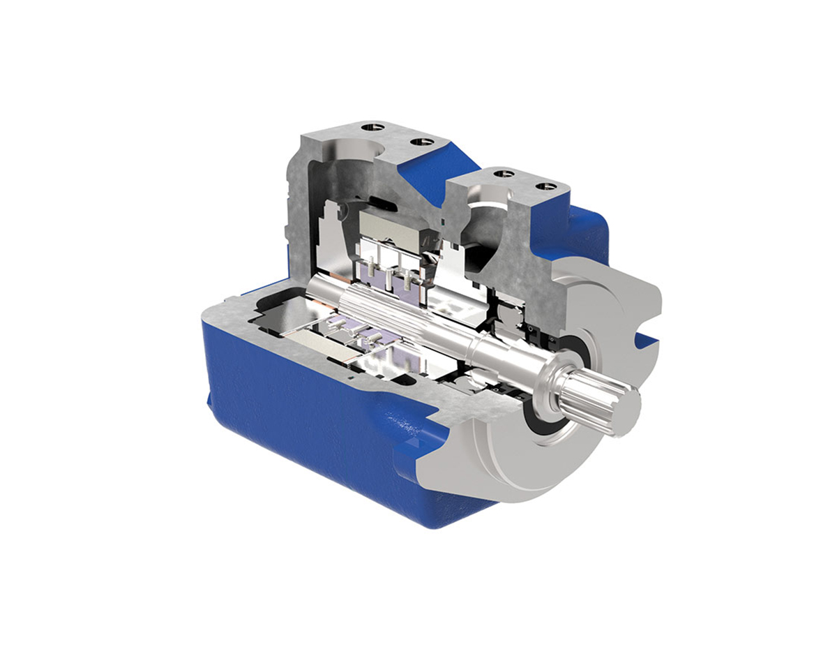
Our Test Bench's used on the Bent Axis Piston Pumps, Hydraulic Piston Motors, Variable Displacement Piston Pumps and Hydraulic Gear Pumps.


Vane pumps are a type of rotary positive displacement pump. A set of paddle-like vanes, mounted radially on a cylindrical rotor, create a number of compartments in which fluid can be trapped and transported through the system. The vanes maintain a close seal against the wall of the pumping chamber preventing fluid from leaking back across the pump. Vane pumps are particularly useful for pumping thin liquids at high pressures. The pumps give low pulsation, accurate flows and have hardened components to resist wear and extend pump life. During a rotation cycle, the volume between adjacent vanes changes because of the rotor’s eccentric mounting position. This creates the pumping action. There are two main types of vane pumps: sliding vane and flexible vane (see Figure 1): In a sliding vane pump, the vanes are fitted into radial slots in a cylindrical rotor. When the pump is stationary, the vanes rest in their slots. However, when the shaft rotates at sufficient speed (about 700 rpm) the vanes travel outwards under centrifugal force, maintaining close contact with a perforated cam ring around the casing wall. The vanes may also be spring-loaded to ensure contact even when the pump is stopped. Any wear occurring at the edge of the vanes is compensated by further extension. In a flexible vane pump, the rotor, or impeller, is made from a flexible material, shaped with several supple lobes that maintain contact with the perforated cam ring and pump casing. The rotor is offset and slightly larger than the pump casing so the vanes are compressed at the ‘short’ side of the cycle and expand again at the opposite side as they conform to the internal shape of the pumping chamber. This action creates separate compartments between the vanes, expanding at the pump inlet to create suction and compressed at the outlet causing discharge. Some wear on the rotor’s lobes can be tolerated since it is larger than the pump casing. Vane pump casings can be balanced, unbalanced or variable. The pumps shown in Figure 1 are unbalanced designs since the rotor is offset: the centre of the drive shaft and the centre of the pump casing are not aligned. Pressure differences between the inlet and outlet can cause vibrations and increased wear on the drive shaft bearings. In a balanced design, the centre of the pump casing and the rotor coincide (see Figure 2). To achieve this, and still create the same functionality, the pumping cavity is elliptical rather than circular. Pairs of inlets and outlets on opposite sides of the pump also cancel out any pressure imbalances. In a variable design, the dimensions of the pumping chamber can be varied. This feature allows the discharge rate of the pump to be adjusted.
_
_
